


We sell wholesale auto parts direct to the public and have warehouses of quality OEM and aftermarket car parts at discount prices. Need help fixing that broken down vehicle? Visit our YouTube how-to videos for DIY auto repair instructions. We offer free shipping on most orders so make us your online auto parts store!


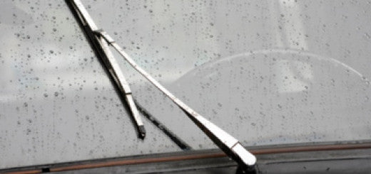

How to Replace a Windshield Wiper Motor and Transmission Linkage Assembly
This set of repair instructions apply to 2005-2009 Pontiac G62008-2012 Chevy Malibu2007-2009 Saturn Aura Often referred to as a Wiper System Module, this is made up of a wiper motor and the...

Automotive Terminology, Codes, Abbreviations and Other Words That Can Be Just Plain Confusing
Most auto technicians and car parts people have a separate language which may not make any sense to the average person trying to work on their car. I am going...
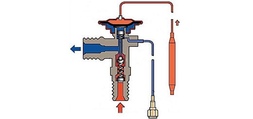

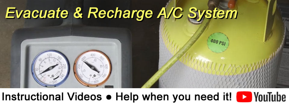
A Basic Description Of Automotive A/C Systems And How They Work
Automotive AC systems can be intimidating if you are to jump in headfirst without a little background on exactly what is happening inside the system. I am writing this article...


What are Hollander Part Numbers?!
People often ask why their new part has a “Hollander” part number on it. Is Hollander a brand? What exactly is a Hollander part?! Hollander is nothing more than a...
Popular Items

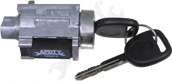
Sale price
$15.95
List price
$24.50

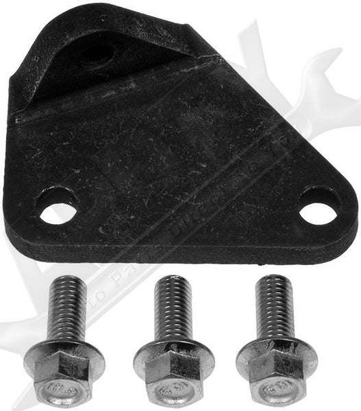
Sale price
$35.37
List price
$54.36

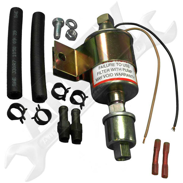
Sale price
$32.56
List price
$50.04

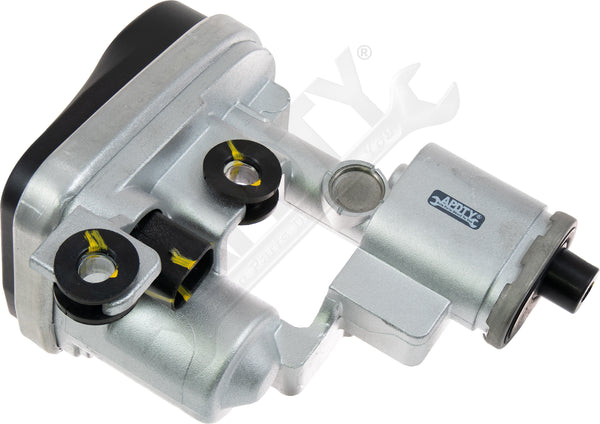
Sale price
$97.17
List price
$149.35

Sale price
$63.60
List price
$97.76

Sale price
$73.46
List price
$112.91


Sale price
$78.97
List price
$121.38